Reverse Engineering and Flashing iPXE to Tenda Gigabit NIC
Tenda Gigabit NIC and PXE booting
I had a Tenda Gigabit NIC laying around and noticed it contained 2 chips on it which looked to be like EEPROM and flash chips and was curious on what I could do with them. It is common for NICs to contain an option rom (OPROM) which runs during boot allowing the user to PXE boot an operating system. Usually these OPROMs are proprietary programs and can’t be hacked to support additional features beyond standard booting, but there is an open-source project iPXE which supports lots of additional features.
In this post, I will show you how to extract the stock firmware and EEPROM from the card, and how to replace it with iPXE.
iPXE
iPXE is an open-source network boot firmware which contains lots of features such as scriptable PXE booting, booting from multiple protocols (HTTP, HTTPS, iSCSI, and more). This is great as not everyone wants to setup a TFTP server to perform traditional PXE booting, and the scripting feature is amazing.
iPXE can be configured to be chain-loaded, meaning traditional PXE OPROMs can boot and load iPXE from the server which then takes over. This is the easiest option, but let’s take a peek into how to burn the OPROM directly onto the card, speeding this up.
Inspecting the Board
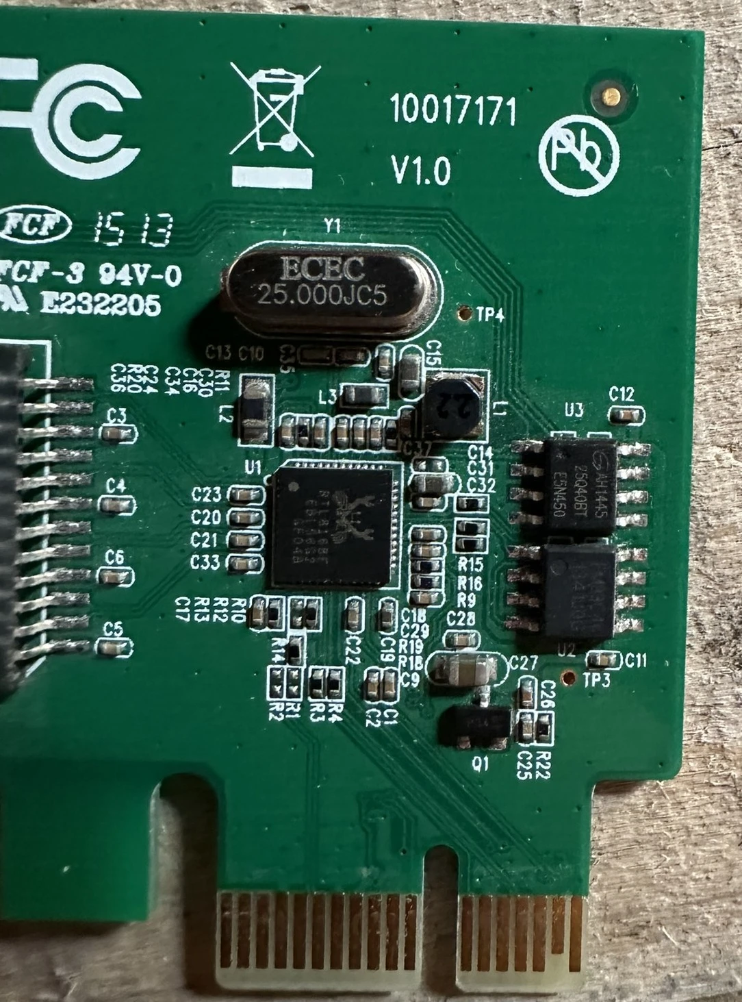
Looking closely, there are 3 main chips of interest:
- NIC controller: RTL8168E
- Flash chip: AH1445 25Q40BT
- EEPROM chip: FM93C46
NIC Controller
The NIC is a RTL8168E Realtek 1G chip. From the datasheet we can see that it supports an OPROM as well as various configurable values (MAC address, etc…) and it seems to be well documented.
EEPROM
Usually EEPROM is used to store some sort of configuration (that can be modified) for embedded systems. Looking at the datasheet for it, we can see that it is a 1024-Bit EEPROM organized as a 64 x 16 bit array so a total of 128 bytes. This is way too small for an OPROM, so we will assume this is for configuration and not the PXE booting ROM.
Flash
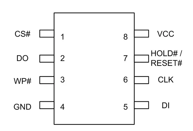
From the datasheet, we can see it is a 128 Mbit 3v SPI/QSPI serial flash chip which has some security features like write protection and a unique ID. This is much larger than the EEPROM and where I would suspect the PXE ROM to be located.
Trying to read the EEPROM
Software Approach
The easiest way is to use ethtool to dump the EEPROM contents. This works on some NICs, but not on this one…
└─# ethtool -e eth0
Cannot get EEPROM data: Operation not supported
It seems like the NICs you can dump the EEPROM on are ones that support this IOCTL command in their driver. I noticed that the driver automatically loaded by Linux was not the specific/official driver for RTL8168E so I decided to look at Realtek’s offical driver to see if it implemented this IOCTL command.
Poking around, I saw that it did!
static int ethtool_ioctl(struct ifreq *ifr)
{
        struct net_device *dev = __dev_get_by_name(ifr->ifr_name);
        void *useraddr = (void *) ifr->ifr_data;
        u32 ethcmd;

       ...
        case ETHTOOL_GEEPROM:
                return ethtool_get_eeprom(dev, useraddr);
After building and loading it (had to unload the existing Linux driver first), I was able to dump the EEPROM. Fantastic!
┌──(gfoudree㉿nzxt-desktop)-[/tmp/r8168-8.052.01]
└─$ sudo ethtool -e enp6s0
Offset		Values
------		------
0x0000:		29 81 ec 10 68 81 ec 10 23 01 04 01 1c 60 c8 3a
0x0010:		35 d2 03 97 05 0f c3 ff 54 8a c0 8c 80 02 00 00
0x0020:		11 3c 07 00 10 20 76 00 63 01 01 ff 00 13 aa 03
0x0030:		02 20 4a 19 80 02 00 20 04 40 20 00 04 40 20 3f
0x0040:		00 00 20 b9 6a 98 60 00 0a 00 e0 00 68 4c 00 00
0x0050:		01 00 00 00 ac 6b 75 80 8d 75 7b 01 a9 c0 48 00
0x0060:		00 00 00 00 00 00 00 00 00 00 00 00 00 00 00 00
0x0070:		00 00 00 00 00 00 00 00 00 00 00 00 00 00 00 00
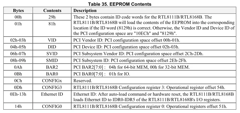
Unfortunately this data seems rather uninteresting. There are no strings and from the RTL8168E datasheet it looks like the main things stored here are the MAC address, PCI configuration and a RTL8168 configuration register (important later). The full details can be found in the datasheet
Trying to read the flash
The flash is a bit trickier, ethtool doesn’t support dumping it even with the Realtek driver. Flashrom is a handy program to read/write to flash chips and sometimes supports talking directly to the NIC without a programmer, but listing the supported devices does not show support for our RTL8168 chip unfortunately.
└─# flashrom -L | grep RTL
Realtek RTL8139/8139C/8139C+  10ec:8139  OK
Realtek RTL8169               10ec:8169  Untested
Looks like we’ll have to try and read this via the hardware route. A SOIC-8 Clip is handy to do this as you can just “clip” on to the chip instead of having to solder anything.
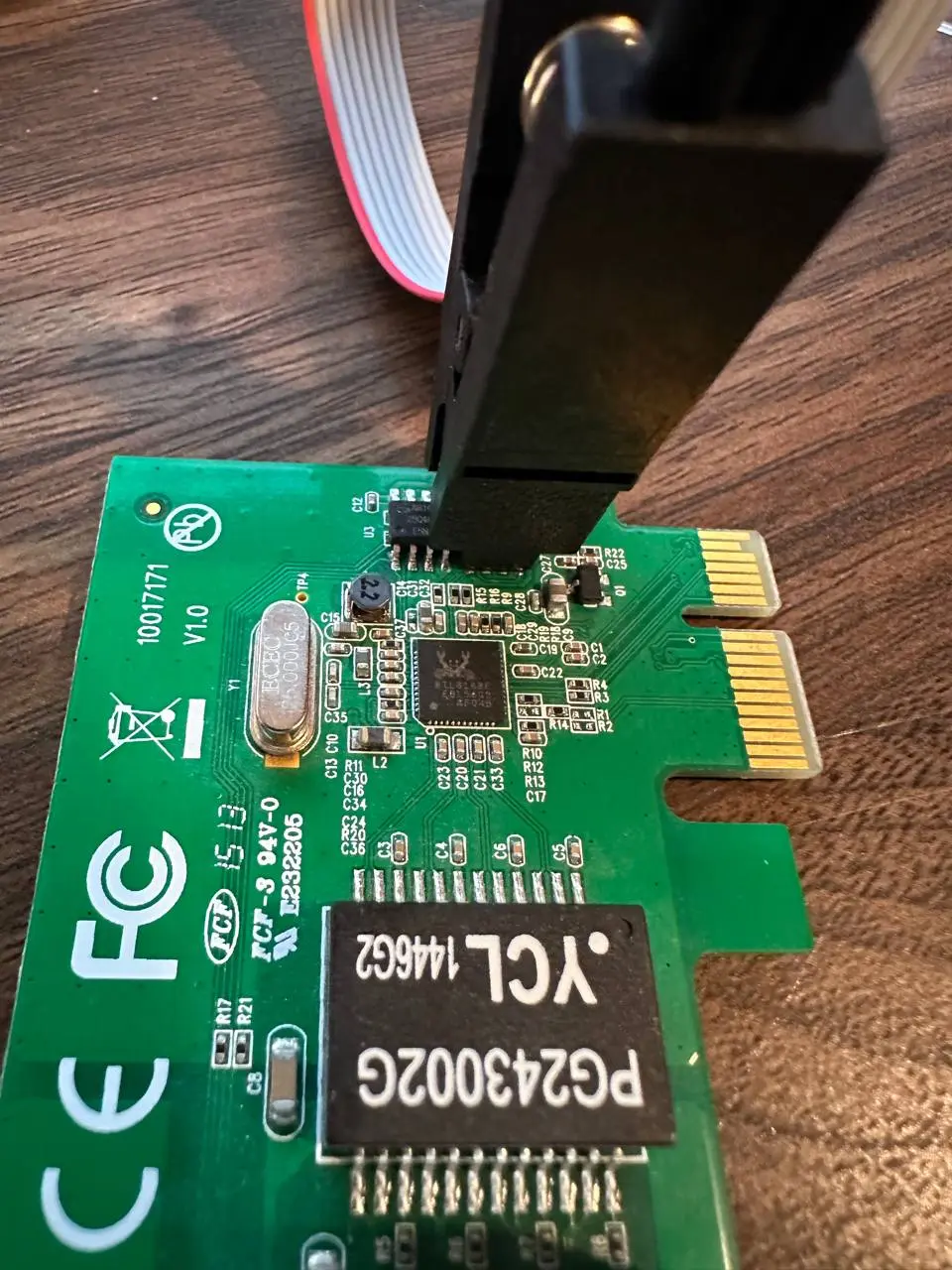
I wrote up some code for an Arduino to talk SPI to the chip and start reading the flash, but for some odd reason it did not want to work. After double-checking the connections, I decided to use a logical analyzer and use PulseView to see what was going on…
Without sending any SPI commands, the moment the chip was powered up from my Arduino, it appears as if the RTL8168 chip got powered up as well and started talking to the flash chip, colliding with my attempts to talk to the flash chip via my Arduino. Clearly this was not going to work so it is time to desolder the chip so we can talk to it on its own.
After removing the chip, it was a good time to confirm the datasheet and my wiring was correct by putting a strong light under the PCB and examining the traces.
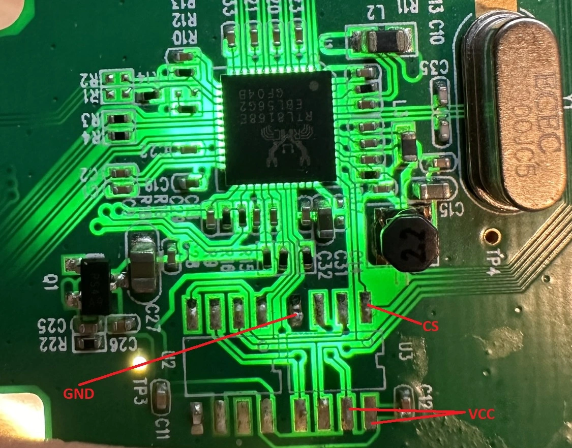
We can determine the GND pin by looking at the ground plane it is attached to and by testing continuity with a multimeter between it and the GND pin of the PCI card. VCC is confirmed by also checking continuity to the PCI VCC pin. Spot checking the others, CS routes to the RTL8168 chip as it should. Datasheet looks correct!
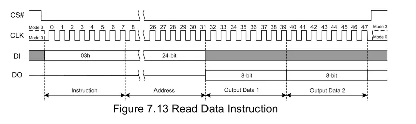
I didn’t have a flash chip reader (like the CH341A) handy, so I wrote a simple Arduino program to talk SPI to the chip and read it. Going off the datasheet again, it seems like the format is:
- Bring CS (chip select) LOW
- Issue read command over SPI, CMD = 0x3
- Issue 24-bit address over SPI
- Read data from SPI that the chip sends
- Bring CS HIGH
#include <SPI.h>
#include <string.h>

void read_page(word page_num) {
  byte buf[512] = {0};
  digitalWrite(CS, LOW);
  SPI.transfer(0x3); // Read command
  SPI.transfer((page_num >> 8) & 0xFF);
  SPI.transfer((page_num >> 0) & 0xff);
  SPI.transfer(0);

  for (int i = 0; i < 256; i++) {
    buf[i] = SPI.transfer(0);
  }
  digitalWrite(CS, HIGH);

  for (int i = 0; i < 256; i++) {
    if (buf[i] < 16) {
      Serial.print("0");
    }
    Serial.print(buf[i], HEX);
    Serial.print(" ");
  }
}

void dump_rom() {
  for (int i = 0; i < 1024; i++) {
    read_page(i);
  }
  Serial.print("\n");
}

void setup() {
  delay(5000);
  Serial.begin(115200);
  Serial.println("Starting...");

  pinMode(WP, OUTPUT);
  pinMode(CS, OUTPUT);

  digitalWrite(WP, HIGH);

  SPI.begin(CLK, DO, DI, CS);
  SPI.setDataMode(0);

  dump_rom();
}

void loop() {
}
I wrote a simple Python script to take the serial output from the Arduino and dump it to binary file
from pwn import *

s = serialtube(port='/dev/ttyUSB0', baudrate=115200)

dta = s.recvline()
dta = s.recvline().decode()


parsed = dta.replace('\n', '')
parsed = parsed.replace(' ', '')

binary = unhex(parsed)

f = open('/tmp/dump.bin', 'wb')
f.write(binary)
f.close()
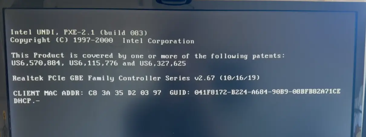
Looking at the dumped flash, we can clearly see this is the PXE OPROM as OPROMs start with 0x55AA in the header and we can see the common string shown during BIOS boot for PXE booting: “Intel UNDI PXE”
└─$ xxd flashdump.bin
00000000: 55aa 14e8 ec0f cb61 bc01 0000 0000 0000  U......a........
00000010: 0000 0000 0000 2000 4000 6000 8d64 2400  ...... .@.`..d$.
00000020: 554e 4449 166b 0000 0102 a70c 0008 b0c4  UNDI.k..........
00000030: b43b 5043 4952 8da4 2400 0000 008d 4900  .;PCIR..$.....I.
00000040: 5043 4952 ec10 6881 0000 1c00 0302 0000  PCIR..h.........
00000050: 1400 0102 0080 0800 0000 0000 3681 0000  ............6...
00000060: 2450 6e50 0102 0000 00c0 0000 0000 af00  $PnP............
00000070: 9201 0200 00e4 0000 0000 d80b 0000 0000  ................
00000080: 0d0a 436f 7079 7269 6768 7420 2843 2920  ..Copyright (C)
00000090: 3139 3937 2d32 3030 3020 2049 6e74 656c  1997-2000  Intel
000000a0: 2043 6f72 706f 7261 7469 6f6e 0d0a 0049   Corporation...I
000000b0: 6e74 656c 2043 6f72 706f 7261 7469 6f6e  ntel Corporation
000000c0: 0049 6e74 656c 2055 4e44 492c 2050 5845  .Intel UNDI, PXE
000000d0: 2d32 2e31 2028 6275 696c 6420 3038 3329  -2.1 (build 083)
000000e0: 000d 0a54 6869 7320 5072 6f64 7563 7420  ...This Product
000000f0: 6973 2063 6f76 6572 6564 2062 7920 6f6e  is covered by on
00000100: 6520 6f72 206d 6f72 6520 6f66 2074 6865  e or more of the
00000110: 2066 6f6c 6c6f 7769 6e67 2070 6174 656e   following paten
00000120: 7473 3a20 200d 0a00 5553 362c 3537 302c  ts:  ...US6,570,
00000130: 3838 342c 2055 5336 2c31 3135 2c37 3736  884, US6,115,776
00000140: 2061 6e64 2055 5336 2c33 3237 2c36 3235   and US6,327,625
00000150: 0d0a 000d 0a52 6561 6c74 656b 2050 4349  .....Realtek PCI
00000160: 6520 4742 4520 4661 6d69 6c79 2043 6f6e  e GBE Family Con
00000170: 7472 6f6c 6c65 7220 5365 7269 6573 2076  troller Series v
00000180: 322e 3536 2028 3037 2f30 312f 3133 290d  2.56 (07/01/13).
00000190: 0a00 5265 616c 7465 6b20 5058 4520 4230  ..Realtek PXE B0
000001a0: 3020 4430 3000 8bff f2e6 00f0 0000 0000  0 D00...........
...
Now, can we replace this with iPXE? :)
Building iPXE
For the OPROM to be valid, we need to set the PCI VID and PID correctly which can be obtained with lspci
└─$ lspci -nn | grep Realtek
03:00.0 Ethernet controller: Realtek Semiconductor Co., Ltd. RTL8111/8168/8411 PCI Express Gigabit Ethernet Controller [10ec:8168] (rev 06)
I added some features by modifying config/general.h to add HTTPS, iSCSI, VLAN, ICMP, and NTP features and then built iPXE with make bin/10ec8168. (the 10ec8168 part comes from the lspci command above with the VID/PID).
Flashing iPXE
Some extra code is necessary to be able to write to the flash chip. Add the iPXE OPROM as a C byte array by running xxd -i bin/10ec8168.rom which we can then use in our C code to write each byte out to the flash chip.
To write, we need to:
- Enable write, CMD = 0x6
- Erase the region, CMD = 0xC7
- Enable Write, CMD = 0x6
- Send page program, CMD = 0x2
- Send 24-bit address
- Send page data
- Check write status register, CMD = 0x5, check bit 1
- Loop
unsigned char bin_10ec8168_rom[] = {...};
unsigned int bin_10ec8168_rom_len = 98304;

void chip_erase() {
  digitalWrite(CS, LOW);
  SPI.transfer(0x6);
  digitalWrite(CS, HIGH);
  digitalWrite(CS, LOW);
  SPI.transfer(0xc7); // Erase
  digitalWrite(CS, HIGH);
}

void write_page(word page_num, byte *buf) {
  chk_write_status();

  digitalWrite(CS, LOW);
  SPI.transfer(0x6); // Must do write enable before any write/erase
  digitalWrite(CS, HIGH);
  delayMicroseconds(100);
  digitalWrite(CS, LOW);

  SPI.transfer(0x2); // Page program

  // Convert to 24-bit address
  SPI.transfer((page_num >> 8) & 0xFF);
  SPI.transfer((page_num >> 0) & 0xFF);
  SPI.transfer(0);

  for (int i = 0; i < 256; i++) {
    SPI.transfer(buf[i]);
  }

  digitalWrite(CS, HIGH);
}

void chk_write_status() {
  byte res = 0xff;
  while (res & 1) {
    delay(100);

    digitalWrite(CS, LOW);
    SPI.transfer(0x5);
    res = SPI.transfer(0);
    digitalWrite(CS, HIGH);
  }
}

void flash_ipxe() {
  chip_erase();
  Serial.print("Writing page: ");
  for (int i = 0; i < bin_10ec8168_rom_len/256; i++) {
    byte buf[256];

    for (int j = 0; j < 256; j++) {
      buf[j] = bin_10ec8168_rom[i*256 + j];
    }
    Serial.print(i);
    Serial.print(" ");
    write_page(i, buf);
  }

  Serial.println("Done!");
}
Success! And you can dump the flash with the previous program and compare the hash to the built iPXE ROM to confirm it was successful.
Testing the card
After resoldering the flash chip to the NIC and putting it back into the PC, I tried to boot it up and select the “Realtek Boot Agent” option from the BIOS menu and expected iPXE to run, but it did not - I was greeted with the old OPROM that we dumped in the beginning that should have been overwritten. How?
Back to the EEPROM
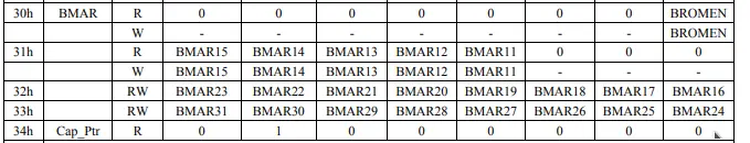
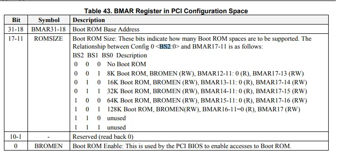
Looking at the RTL8168 datasheet, there is some interesting information exposed via the registers (which is used during boot by the BIOS to find OPROMs). The 32-bit register at 0x30 is the BMAR register which contains the OPROM base address (BMAR) + the ROM size (ROMSIZE) and if it is enabled (BROMEN). Let’s have a look at the values…
┌──(gfoudree㉿nzxt-desktop)-[/tmp/r8168-8.052.01]
└─$ setpci -s 06:00.0 0x30.B
00

┌──(gfoudree㉿nzxt-desktop)-[/tmp/r8168-8.052.01]
└─$ setpci -s 06:00.0 0x31.B
00

┌──(gfoudree㉿nzxt-desktop)-[/tmp/r8168-8.052.01]
└─$ setpci -s 06:00.0 0x32.B
10

┌──(gfoudree㉿nzxt-desktop)-[/tmp/r8168-8.052.01]
└─$ setpci -s 06:00.0 0x33.B
97
So the BMAR register reads as 0x97100000 which seems okay, but the ROMSIZE and BROMEN registers are 0 which means it is disabled! No wonder iPXE isn’t working…
Going back to the EEPROM I dumped earlier, there was a CONFIG0 register which contained configuration values for the RTL8168 chip. Looking at the datasheet further, we can see there’s 3 bits which configure the size of the boot rom located inside the byte at 0x51.
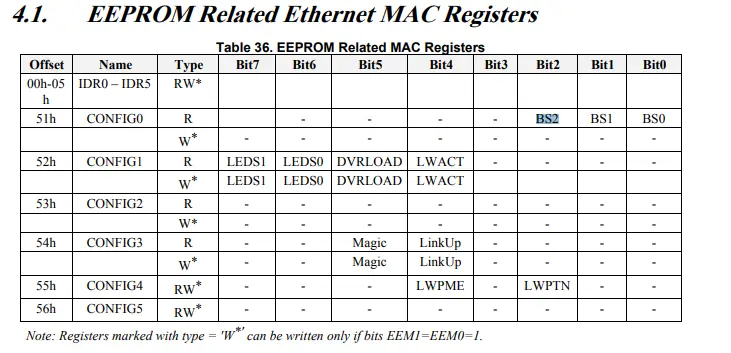
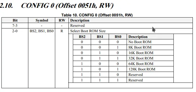
If you look back up where the EEPROM was dumped, you can see the value for this byte at 0x51 is 0x00 which means it is configured as “No Boot ROM” which concurs with values read from the PCI registers. Perhaps there is a correlation here.
0x0050: 01 00 00 00 ac 6b 75 80 8d 75 7b 01 a9 c0 48 00
Since we know the size of the Boot ROM (128K), the value should be BS2 = 1, BS1 = 0, BS0 = 1 or the whole register (CONFIG0) set to 0x5. Let’s see if we can try and set it with ethtool…
┌──(gfoudree㉿nzxt-desktop)-[/tmp/r8168-8.052.01]
└─$ sudo ethtool -E enp6s0 offset 0x51 length 1 value 0x5
Cannot set EEPROM data: Operation not supported
Sometimes there’s a “magic” value that the driver checks as a parameter from ethtool to guard against accidental writes source which you pass via the magic parameter to ethtool. I tried many different values (0xdeadbeef, 0x0badbeef, etc) looking through the driver source and trying things from there, but none worked. I suppose we will have to write to it with hardware just like the flash chip…
Flashing the EEPROM
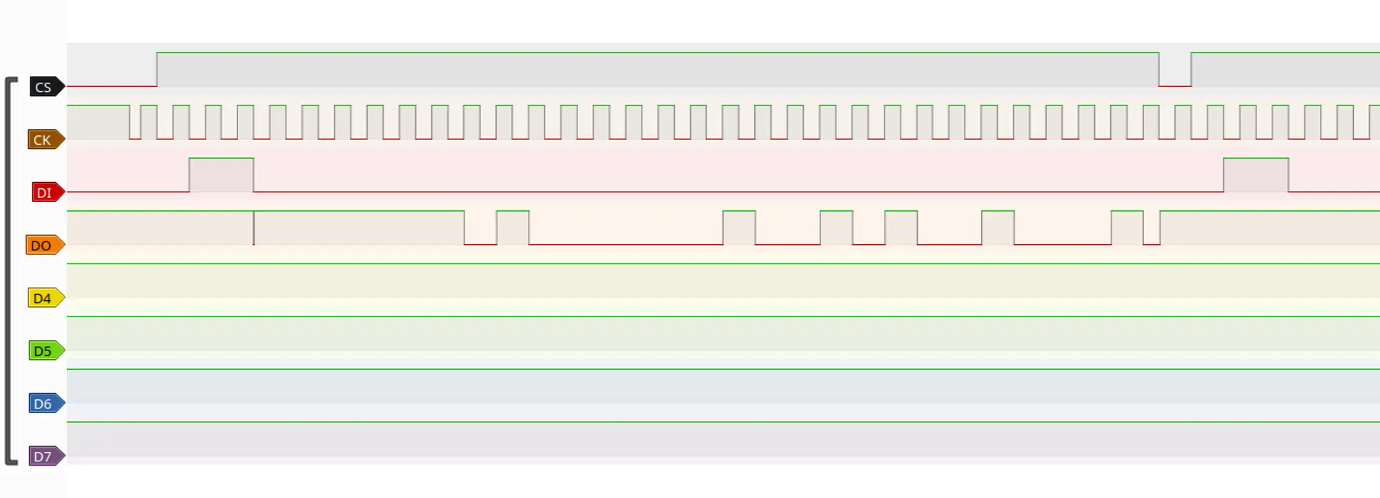
Unfortunately, unlike the flash chip which used SPI, the EEPROM uses the MICROWIRE protocol which takes some extra work to get going. Thankfully someone wrote a library to do this, although I was successful in bitbanging the protocol going off the timing diagrams from the datasheet.
For some reason, the bytes were swapped so I wrote 0x5 to the address 0x50.
#include "93C46.h"

#define pCS 37
#define pSK 38
#define pDI 39
#define pDO 40

void setup() {
  bool longMode = EEPROM_93C46_MODE_8BIT;

  eeprom_93C46 e = eeprom_93C46(pCS, pSK, pDI, pDO);
  e.set_mode(longMode);
  Serial.begin(115200);

  int len = longMode ? 64 : 128;
  word readBuffer[len];
  for(int i = 0; i < len; i++) {
    // Read by address
    word r = e.read(i);
    readBuffer[i] = r;

    byte b1 = r & 0xff;


    if (b1 < 16) {
      Serial.print(0, HEX);
    }
    Serial.print(b1, HEX);
    Serial.print(" ");
  }
  Serial.println();

  word config = e.read(0x50);
  byte b1 = (config & 0xff);
  byte b2 = e.read(0x51);
  Serial.print(" ");
  Serial.print(b1, HEX);
  Serial.print(" ");
  Serial.print(b2, HEX);
  Serial.println();

  e.ew_enable();
  e.write(0x51, 0x01);
  e.write(0x50, 0x05);

  config = e.read(0x50);
  b1 = (config & 0xff);
  b2 = e.read(0x51);
  Serial.print(" ");
  Serial.print(b1, HEX);
  Serial.print(" ");
  Serial.print(b2, HEX);
  Serial.println();
}

void loop() {}
Trying again
After resoldering everything and trying to boot again, the same problem occured. Time to debug the BIOS and see why the OPROM is getting passed over.
QEMU + Seabios Debugging
Seabios is an opensource BIOS implementation which supports verbose logging during boot and even attaching with GDB while running inside of QEMU (x86 emulator). To debug the PCI card, we will need to pass it through via PCI-passthrough to the QEMU instance so that Seabios can attempt to enumerate it and run the OPROM on the card.
Enabling PCI-passthrough on Linux
First we must enable IOMMU which allows the CPU and MMU to isolate a memory region for the VM. More details
I have an Intel desktop, so we must add the following to the Linux kernel cmdline in /boot/grub/grub.cfg
intel_iommu=on iommu=pt
# Example: GRUB_CMDLINE_LINUX_DEFAULT="apparmor=1 security=apparmor udev.log_priority=3 iommu=pt intel_iommu=on"
Then update grub and reboot.
sudo grub-mkconfig -o /boot/grub/grub.cfg
reboot
Check if the IOMMU was enabled correctly (we can see the iommu groups being populated and “IOMMU enabled”)
└─$ sudo dmesg | grep -i IOMMU
[    0.000000] Command line: BOOT_IMAGE=/boot/vmlinuz-6.8-x86_64 root=UUID=4cb39bdb-5857-459b-be4f-993bb0a40160 rw apparmor=1 security=apparmor udev.log_priority=3 iommu=pt intel_iommu=on
[    0.037633] Kernel command line: BOOT_IMAGE=/boot/vmlinuz-6.8-x86_64 root=UUID=4cb39bdb-5857-459b-be4f-993bb0a40160 rw apparmor=1 security=apparmor udev.log_priority=3 iommu=pt intel_iommu=on
[    0.037677] DMAR: IOMMU enabled
[    0.085607] DMAR-IR: IOAPIC id 2 under DRHD base  0xfed91000 IOMMU 0
[    0.274876] iommu: Default domain type: Passthrough (set via kernel command line)
[    0.301886] pci 0000:00:00.0: Adding to iommu group 0
[    0.301893] pci 0000:00:01.0: Adding to iommu group 1
[    0.301899] pci 0000:00:06.0: Adding to iommu group 2
[    0.301904] pci 0000:00:0a.0: Adding to iommu group 3
[    0.301909] pci 0000:00:0e.0: Adding to iommu group 4
[    0.301919] pci 0000:00:14.0: Adding to iommu group 5
[    0.301924] pci 0000:00:14.2: Adding to iommu group 5
[    0.301929] pci 0000:00:14.3: Adding to iommu group 6
[    0.301941] pci 0000:00:15.0: Adding to iommu group 7
[    0.301945] pci 0000:00:15.1: Adding to iommu group 7
[    0.301950] pci 0000:00:15.2: Adding to iommu group 7
[    0.301957] pci 0000:00:16.0: Adding to iommu group 8
[    0.301962] pci 0000:00:17.0: Adding to iommu group 9
[    0.301970] pci 0000:00:1a.0: Adding to iommu group 10
[    0.301978] pci 0000:00:1b.0: Adding to iommu group 11
[    0.301997] pci 0000:00:1c.0: Adding to iommu group 12
[    0.302004] pci 0000:00:1c.1: Adding to iommu group 13
[    0.302011] pci 0000:00:1c.2: Adding to iommu group 14
[    0.302021] pci 0000:00:1d.0: Adding to iommu group 15
[    0.302028] pci 0000:00:1d.4: Adding to iommu group 16
[    0.302042] pci 0000:00:1f.0: Adding to iommu group 17
[    0.302048] pci 0000:00:1f.3: Adding to iommu group 17
[    0.302054] pci 0000:00:1f.4: Adding to iommu group 17
[    0.302060] pci 0000:00:1f.5: Adding to iommu group 17
[    0.302069] pci 0000:01:00.0: Adding to iommu group 18
[    0.302076] pci 0000:01:00.1: Adding to iommu group 18
[    0.302081] pci 0000:02:00.0: Adding to iommu group 19
[    0.302095] pci 0000:06:00.0: Adding to iommu group 20
[    0.302102] pci 0000:07:00.0: Adding to iommu group 21
[    0.302109] pci 0000:09:00.0: Adding to iommu group 22
Then we need to identify the PCI device we want to passthrough (10ec:8168)
└─$ lspci -vvn -s 06:00.0                                                                                                                                               130 ⨯
06:00.0 0200: 10ec:8168 (rev 06)
	Subsystem: 10ec:0123
	Control: I/O+ Mem+ BusMaster- SpecCycle- MemWINV- VGASnoop- ParErr- Stepping- SERR- FastB2B- DisINTx-
	Status: Cap+ 66MHz- UDF- FastB2B- ParErr- DEVSEL=fast >TAbort- <TAbort- <MAbort- >SERR- <PERR- INTx-
	Interrupt: pin A routed to IRQ 17
	IOMMU group: 20
	Region 0: I/O ports at 5000 [size=256]
	Region 2: Memory at 97120000 (64-bit, non-prefetchable) [size=4K]
	Region 4: Memory at 4004100000 (64-bit, prefetchable) [size=16K]
	Expansion ROM at 97100000 [disabled] [size=128K]
	Capabilities: <access denied>
	Kernel driver in use: r8169
	Kernel modules: r8169
Here we can see that the OPROM is enumerated but marked as disabled. Also, r8169 is the current driver in use which we need to unbind so that we can use VFIO to pass it to QEMU.
# Add device to VFIO so it grabs it
echo 10ec 8168 > /sys/bus/pci/drivers/vfio-pci/new_id

# Unbind device from current driver
echo 0000:06:00.0 > /sys/bus/pci/drivers/r8169/unbind

# Install VFIO module
modprobe vfio_pci ids=10ec:8168
Check that it worked…
└─$ ls /dev/vfio
20  devices  vfio
Great!
Building Seabios
We want to make a verbose debugging build of Seabios by setting the level to 8, and also enabling the special debug IO port which allows QEMU to get the debug info from Seabios at runtime.
git clone https://github.com/qemu/seabios.git
make menuconfig

# Set Debugging -> Debug Level = 8
# Debugging -> Special IO port debugging = True

make -j
Running it all
Pass in the bios.bin file from the Seabios build along with the PCI device information 06:00.0 and be sure to disable the standard NIC QEMU automatically adds with -net none. The -device isa-debugcon,iobase=0x402,chardev=seabios command is what accesses the debug IO port Seabios sends messages to so we can see them.
sudo qemu-system-x86_64 -m 128 -bios out/bios.bin -chardev stdio,id=seabios \
-device isa-debugcon,iobase=0x402,chardev=seabios -net none -device vfio-pci,host=06:00.0 -enable-kvm
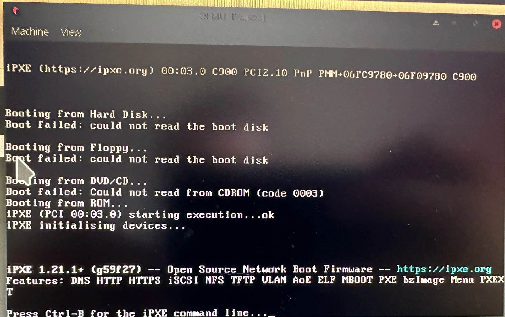
Looking at the debug logs from QEMU, we can see that Seabios finds the OPROM and executes it.
Attempting to init PCI bdf 00:03.0 (vd 10ec:8168)
Attempting to map option rom on dev 00:03.0
Option rom sizing returned febc0000 fffe0000
Inspecting possible rom at 0xfebc0000 (vd=10ec:8168 bdf=00:03.0)
Copying option rom (size 98304) from 0xfebc0000 to 0x000c9000
Checking rom 0x000c9000 (sig aa55 size 192)
Running option rom at c900:0003
Success!!
Trying with UEFI
QEMU can also run with UEFI instead of a legacy BIOS. Tianocore OVMF is great for this and instructions to build it can be found here.
git clone https://github.com/tianocore/edk2.git
cd edk2
git submodule update --init
make -C BaseTools -j
source edksetup.sh
cd ../
make -C edk2/BaseTools
Add the following to edk2/Conf/target.txt
TARGET                = DEBUG
TARGET_ARCH           = X64
TOOL_CHAIN_TAG        = GCC5
Then:
build -p OvmfPkg/OvmfPkgX64.dsc
sudo qemu-system-x86_64 -bios /tmp/edk2/Build/OvmfX64/DEBUG_GCC5/FV/OVMF.fd -net none \
 -debugcon file:debug.log -global isa-debugcon.iobase=0x402 -device vfio-pci,host=06:00.0
Looking at the video output, the iPXE OPROM does not run (just like in the physical computer). This is confirmed by the debug logs which shows it “processes” OPROM and shows it as being present, but nothing else in the log indicates that it runs it or attempts to do so. Strange.
Process Option ROM: BAR Base/Length = 81000000/20000
PciBus: Resource Map for Root Bridge PciRoot(0x0)
Type =   Io16; Base = 0xC000;	Length = 0x1000;	Alignment = 0xFFF
   Base = 0xC000;	Length = 0x100;	Alignment = 0xFF;	Owner = PCI [00|03|00:10]
   Base = 0xC100;	Length = 0x10;	Alignment = 0xF;	Owner = PCI [00|01|01:20]
Type =  Mem32; Base = 0x80000000;	Length = 0x1100000;	Alignment = 0xFFFFFF
   Base = 0x80000000;	Length = 0x1000000;	Alignment = 0xFFFFFF;	Owner = PCI [00|02|00:10]; Type = PMem32
   Base = 0x81000000;	Length = 0x20000;	Alignment = 0x1FFFF;	Owner = PCI [00|00|00:00]; Type =  OpRom
   Base = 0x81020000;	Length = 0x1000;	Alignment = 0xFFF;	Owner = PCI [00|02|00:18]
Type =  Mem64; Base = 0xC000000000;	Length = 0x100000;	Alignment = 0xFFFFF
   Base = 0xC000000000;	Length = 0x4000;	Alignment = 0x3FFF;	Owner = PCI [00|03|00:20]; Type = PMem64
   Base = 0xC000004000;	Length = 0x1000;	Alignment = 0xFFF;	Owner = PCI [00|03|00:18]
Conclusion
I am not 100% sure, but my guess is that the PC I originally ran the card on was a modern UEFI system which did not support running the older OPROM or there was some sort of misconfiguration going on. It doesn’t explain why the original OPROM did run, however. I remain somewhat puzzled, but happy that the flashed iPXE ROM does finally run.